Packard Bell Tacoma M/Board

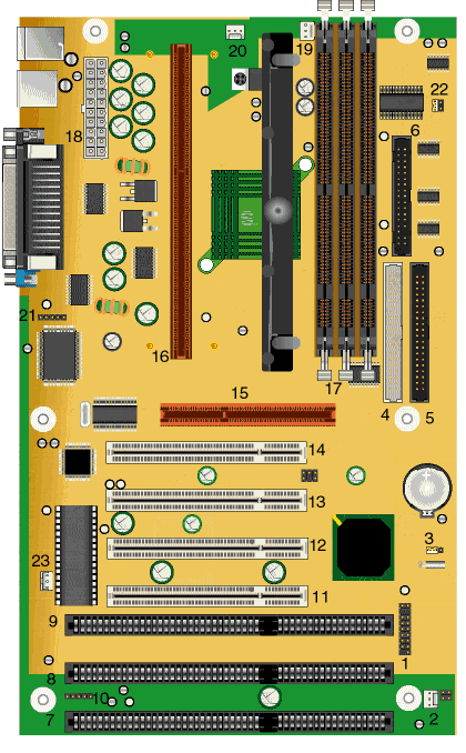
| Item | Description | Item | Description |
|---|
| 1 | Front Panel Connector | 2 | SFAN1 |
| 3 | CMOS Clear/Keep | 4 | Secondary IDE Connector |
| 5 | Primary IDE Connector | 6 | FDD Connector |
| 7 | ISA Connector 3 | 8 | ISA Connector 2 |
| 9 | ISA Connector 1 | 11 | PCI Slot 4 |
| 12 | PCI Slot 3 | 13 | PCI Slot 2 |
| 14 | PCI Slot 1 | 15 | AGP Connector |
| 16 | PII SLOT 1 | 17 | DIMM Sockets |
| 18 | Main Power Input | 19 | CPU FAN 1 |
| 20 | PSFAN 2 | 21 | IRDA Header |
| 22 | Power On Mode Jumper | 23 | Wake on LAN connector |
Specification
- Battery : 3.3V, 100mAH lithium battery, in socket.
- BIOS : MSI system BIOS with AMI core. 2MB Flash Device.
- Bus : Both 66 MHz and 100 MHz front side bus is supported.
- Cache : Integrated on the SEC cartridge.
- Chipset : Intel 82440BX PCI set (82443BX PCI/AGP controller (PAC) and 82371EB PCI/ISA IDE Xcelerator (PIIX4E) device).
- CPU : SECC cartridge, placed in SLOT 1: Pentium II, Pentium III, Celeron.
- Expansion Slots : 2 ISA slots, 3 PCI slots, 1 shared ISA/PCI slot, 1 AGP slot.
- Form Factor : ATX Form Factor 30cm. x 18.6cm.
- RAM : Three 168 pin DIMM sockets supporting up to 768 MB of SDRAM memory.
- Video : None.
Upgrade Options
- CPU :
- CPU upgradable using Pentium II up to 450 MHz, Pentium III up to 600 MHz (See note in "Known Issues" section regarding Coppermine PIII processors), and Celeron up to 433 MHz.
- RAM :
- Upgradable up to 768 MB using 3.3 V gold-plated SDRAM DIMMs.
- The Tacoma 1.2a motherboard only accepts 168-pin DIMM modules. Only gold-plated DIMMs may be used, as the sockets on the motherboard are also gold-plated, and oxidation must be prevented.
- Only use unbuffered 3.3 V SDRAM.
- Single- or double-sided DIMMs may be used.
- SDRAM DIMMs may be up to 256 MB big.
- Memory size and speed can vary between sockets.
- Parity (×72) DIMMs can be installed, ECC memory checking is supported.
- If the front bus is set to 100 MHz, then memory must be conform to PC100 SDRAM specs.
Jumpers
Note: CPU speed is not configured by jumper; to change it, use the CMOS Setup.
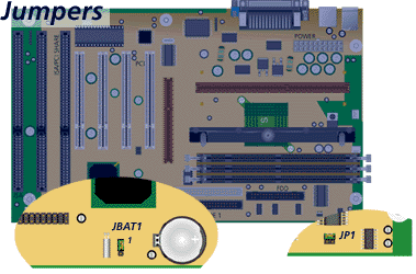
To clear the CMOS data, turn off the system and unplug the power cord for about 10 seconds. Then move jumper JBAT1 from 1-2 to 2-3 and back to 1-2. Then replug the system, start it, enter the BIOS and set default values.
JP1 - 2-pin jumper block for Power On Mode Selection. Closed - System is powered on when the power button is pressed (default). Open - System is powered on immediately when power cable is connected.

J4 - 2-pin jumper for password clear. Closed: Normal operation (default). Open: Clear password.
JP5 - 6-pin jumper block for USB selection. 1-2 4-5: Upper-back USB disabled (front USB enabled). 2-3 5-6: Front USB disabled (upper-back USB enabled)
Known Issues
My Packard Bell computer has a Tacoma motherboard. I would like to upgrade the CPU. Does the motherboard support Pentium III Coppermine processors?
All BIOSes for the Tacoma motherboards from version 1.90 onwards include the microcode for Pentium III Coppermine processors. The actual support of such processor is, howevwer, dependant on the voltage regulator of the motherboard. That regulator must be able to provide the correct voltage for Pentium III Coppermine processors. Tacoma motherboards with part number 6733070700 or higher have such a voltage regulator, thus they support Pentium III Coppermine processors. The part number can be found on a label on the motherboard.


