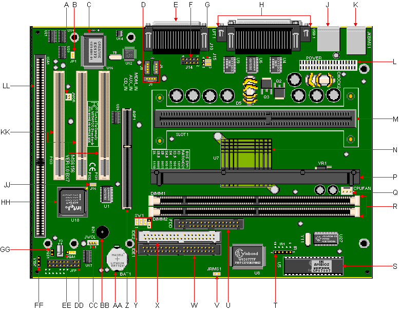

| Item | Description | Item | Description |
|---|---|---|---|
| A | Wake-On-Ring Header | T | IrDA Connector |
| B | Power-On Mode Jumper (JP1) | U | FDD Connector |
| C | Creative Labs ES1373 Audio Chipset | V | Power On/Off Switch Header (JRMS) |
| D | AUX Line In (J5),Modem In (J6) & CD In (J8) | W | Primary IDE Connector |
| E | MIDI/Game Port, Line In, Line Out & Mic In Jacks | X | Secondary IDE Connector |
| F | Front Side USB Header (J14) | Y | Core/Bus Ratio Jumper Block (SW1) |
| G | Front Side USB Select Jumper Block (J15) | Z | AGP Port |
| H | Parallel & Serial Ports | AA | Battery |
| J | Stacked USB Ports | BB | Piezo Speaker |
| K | PS/2 Keyboard & Mouse Ports | CC | Wake-On-LAN Header |
| L | Primary Power Connector | DD | Front Panel Header (J13) |
| M | SEC Processor Cartridge Interface (SLOT1) | EE | CMOS Clear Jumper (JGA1) |
| N | Intel 82443ZXPCI AGP Controller (PAC) | FF | Power Management LED Header (JGL1) |
| P | CPU Heatsink Support Bar | GG | Power Management Switch Header (JGS1) |
| Q | CPU Heatsink Fan Power Header | HH | Intel 82371EB Chipset (PIIX4E) |
| R | DIMM Slots | JJ | Password Clear Jumper (J16) |
| S | Flash BIOS | KK | PCI Slots |
| LL | ISA Slot |
| Jumper | Function | Configuration |
|---|---|---|
| JGA1 | CMOS Clear | 1-2 - Normal Operation 2-3 - Clear CMOS Data |
| J16 | Password Clear | Closed - Normal Operation Open - Clear Password |
| JP1 | Power On Mode | Closed - Select Boot-up by switch (Default) Open - Select Immediate Boot-up/Last State |
| Jumper 1 | Jumper 2 | Jumper 3 | Jumper 4 | Core/Bus Ratio |
|---|---|---|---|---|
| On | Off | On | On | 2.5 |
| On | On | Off | On | 3 |
| On | Off | Off | On | 3.5 |
| On | On | On | Off | 4 |
| On | Off | On | Off | 4.5 |
| On | On | Off | Off | 5 |
| On | Off | Off | Off | 5.5 |
| Off | On | On | On | 6 |
| Off | Off | On | On | 6.5 |
| Off | On | Off | On | 7 |
| Off | Off | Off | On | 7.5 |
| Off | On | On | Off | 8 |
Note - If the CPU is 400MHz then the Core/Bus Ratio is 4.
Cache Upgrade. The 911 motherboard comes with 0, 128K, 256K or 512K Level 2 cache, depending on the processor. The cache is not upgradeable.
RAM Upgrade. Maximum on Motherboard: 256MB. Uses 8/16/32/64/128 MB DIMMs, 60ns or faster SDRAM DIMMs Supports only non-parity DIMM modules. The 168-pin DIMM sockets will support PC66/PC100 unbuffered 3.3V 1MBx64 (8MB), 2MBx64 (16MB), 4MBx64 (32MB), and 8MBx64 (64MB) and 16MBx64 (128MB) SDRAM DIMMs. PC100-compliant (100MHz) DIMMS should be used with any processor operating at 350MHz or faster. Bank 1 will be populated as the default from the factory. No configuration jumpers: BIOS detects memory size, and memory type. This motherboard will not accept 36-bit DIMM modules (parity).