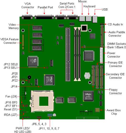

Installing a video expansion card will automatically disable the on board video controller.
Password Clear Jumper
| Jumper | Configuration |
|---|---|
| JP6 | Open - Password Enabled (Default) Close - Password Clear |
Processor Bus/Core Speed Select
| Bus Speed | JP16 | JP17 |
|---|---|---|
| 2/3 Bus/Core Frequency Ratio | 1-2 | 1-2 |
| 1/2 Bus/Core Frequency Ratio | 2-3 | 1-2 |
| 2/5 Bus/Core Frequency Ratio | 2-3 | 2-3 |
| 1/3 Bus/Core Frequency Ratio | 1-2 | 2-3 |
Processor Interface Voltage Select
| CPU Type | JP7 | JP8 | JP9 | JP10 | JP11 |
|---|---|---|---|---|---|
| P54C | 1-2 | 1-2 | 1-2 | 1-2 | 1-2 |
| P55C | 2-3 | 2-3 | 2-3 | 2-3 | 2-3 |
| MII | 1-2 | 1-2 | 1-2 | 1-2 | 1-2 |
Processor Core Voltage Select
| Description | CPU Voltage | JP20 | JP21 | JP22 |
|---|---|---|---|---|
| VR | 3.3V Default | ON | OFF | OFF |
| VRE | 3.52V for 200MHz CPU | OFF | OFF | OFF |
| P55C | 2.8V for P55C CPU | OFF | OFF | ON |
| Cyrix M II | 2.9V | OFF | ON | OFF |
The RTC battery is upgraded by removing and replacing it with a Lithium 3v CR2032 or its equivalent battery in socket BT8J1.
To remove the battery, locate BT8J1 battery socket on the motherboard. Use an index finger and thumb from one hand, grip the battery at opposite points. Lift the battery out of the socket.
Take the upgrade battery, insure that the flat surface is facing up. Snap it into the battery socket. Note - + Positive side faces up.
The cache is not upgradeable.
This motherboard utilizes the Socket 7 (U25), which is a staggered 321 pin Zero Insertion Force (ZIF) socket. This motherboard is designed to be upgradeable with any pin-compatible Intel® Pentium™ processor, AMD or Cyrix M II™ processor, including, but not limited to, the following:
The AMD K6-266 and above require a CPU voltage setting of 2.2 volts. This voltage setting is not supported on this motherboard. Do NOT attempt to upgrade the CPU on this motherboard with any AMD K6 processor 266 or above.
The Cyrix M II 266 is NOT a 266MHz processor. Use the settings listed for a 200MHz processor. These settings are also printed on the surface of the processor itself.
| Processor Freq.(MHz) | SEL0 JP12 | SEL1 JP13 | JP14 | BF0 JP16 | BF1 JP17 | Host Bus Freq.(MHz) |
|---|---|---|---|---|---|---|
| 133 | ON | OFF | OFF | 2-3 | 1-2 | 66 |
| 150 | OFF | ON | ON | 2-3 | 2-3 | 60 |
| 166 | ON | OFF | OFF | 2-3 | 2-3 | 66 |
| 200 | ON | OFF | OFF | 1-2 | 2-3 | 60 |
| * 233 | ON | OFF | OFF | 1-2 | 1-2 | 66 |
| * 266 | ON | OFF | OFF | 1-2 | 2-3 | 66 |
* PB810 Only
The Motherboard has two DIMM sockets configured as two (0-1) banks. The system memory is upgradeable to 128MB. The 168-pin DIMM sockets will accept both 3.3V as well as 3.5V 1MBx64 (8MB), 2MBx64 (16MB), 4MBx64 (32MB), and 8MBx64 (64MB) fast page DRAM DIMM's or extended data out DRAM DIMM's with the recommended access speed of 60ns or faster. This motherboard will accept either single or double sided DIMM's. Memory type, size, and speed can vary between sockets. This motherboard will not accept 36 bit DIMM modules (parity). Due to the nature of the VX controller chipset, this motherboard will not support 128MB DIMM modules.
The only 64MB DIMM that is approved for the 810 is Packard Bell part number 965174.
PB810 - The Motherboard has 2 MB Video Memory, and is not upgradable.
PB820 - Can be upgraded by installing another 1MB of Video Ram.