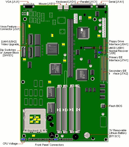

The on-board video chip of your computer will automatically be disabled by the installation of a separate video card.
| Switch | Function | Status | Configuration |
|---|---|---|---|
| 1 | Reserved | On * Off | Reserved Reserved |
| 2 | ISA Speed | On Off | 60 or 66 MHz 50 MHz |
| 3 | Password | On * Off | Disabled Enabled |
| 4 | CMOS | On Off * | Clear Normal |
| 5 | Setup | On Off * | Disabled Enabled |
| 6 | Frequency Multiplier | On Off | 2X 1.5X |
| 7 | CPU Clock 1 | On Off | 60 MHz 50 or 66 MHz |
| 8 | CPU Clock 0 | On Off | 66 MHz 50 or 60 MHz |
* Indicates default settings.
| Jumper | Function | Status | Configuration |
|---|---|---|---|
| J26 | BIOS Recovery | 1-2 2-3 | Normal Recovery |
| J13J1 | CPU Voltage | 1-2 2-3 | VR VRE |
Note - Some configurations of this series of motherboards may list the BIOS Recovery Jumper as J5A2. Both designations are valid. The jumper is in the same location and the settings are the same.
Replace with 3 volt lithium battery.
1. Insert the BIOS update diskette into drive A: and reboot the system.
2. Press (enter). When the dialogue box appears.
3. The Main Menu will appear on the screen.
4. Select "Update Flash Memory Area from a file" using the Down Arrow key.
5. Press (enter).
6. The UPDATE FLASH AREA dialog box appears on the screen.
7. Select "Update System Bios".
8. Press (enter).
9. Select 1006AU0R.BIO file.
10. Press (enter).
11. Press (enter) at the following screen to proceed with programming.
12. After 2 message screens, the BIOS is now re-programmed with the updated BIOS file.
13. Remove the disk from drive A.
14. Press (enter) to reboot the computer system.
15. Complete the process by running the CMOS Setup program.
1. Move the 'FLASH NORMAL/FLASH RECOVERY' jumper block, J5A2 from pins 1-2 to pins 2-3.
2. Insert the BIOS upgrade diskette and reboot the system. No video is available during the procedure.
3. The system beeps once and starts copying the recovery code into the CMOS Flash memory.
4. The system beeps twice as the recovery completes.
5. Turn off the system and move the jumper block, J5A2 from pins 2-3 to pins 1-2.
6. Leave the BIOS upgrade diskette in the floppy drive, and continue with the original upgrade following the procedure described in 'BIOS UPGRADE PROCEDURE'.
This system has got 16KB Internal Cache (integrated into the CPU). The Cache memory on this motherboard CANNOT be upgraded.
This motherboard can accommodate the Intel Pentium P75, P90, P100, P120 and P133MHz, and the 150, 166, 180 and 200MHz Intel Pentium Overdrive Processor with MMX technology.
The upgrade processor installs in the Zero Insertion Force (ZIF) Socket. (U11H1). In the table below you can find the correct jumper settings for each processor:
| Speed | 8 | 6 | 7 | 2 |
|---|---|---|---|---|
| 75MHZ | OFF | OFF | OFF | OFF |
| 90MHZ | OFF | OFF | ON | OFF |
| 100MHZ | ON | OFF | OFF | ON |
| 120MHZ | OFF | ON | ON | ON |
| 133MHZ | ON | ON | OFF | ON |
| MMX 150 Overdrive* | OFF | ON | OFF | ON |
| MMX 166 Overdrive* | ON | OFF | OFF | ON |
| MMX 180 Overdrive* | OFF | ON | ON | ON |
| MMX 200 Overdrive* | ON | OFF | ON | ON |
* The Intel Pentium Overdrive Processor with MMX technology, is equipped with an on-package voltage regulator, which adapts the 3.3V system voltage to 2.8V processor voltage.
If you wish to install an MMX Overdrive processor, it may be necessary to have BIOS version 1.00.07 BY0R and at least 16MB of RAM installed. The current BIOS version will appear on the screen immediately after switching on the computer.
The video memory on this system can be upgraded to 2MB, by using two 256Kx16-70ns SOJ DRAM chips.