The on-board video chip of your computer will automatically be disabled by the installation of a separate video card.
| Jumper | Function | Pin/Setting | Description |
|---|---|---|---|
| J7 | CPU Voltage (5.0V/5.25V) | 1-2 2-3 | 5.00v (60Mhz) 5.25v (66Mhz) |
| J14 | CPU Speed | 1-2 2-3 | 66MHz 60MHz |
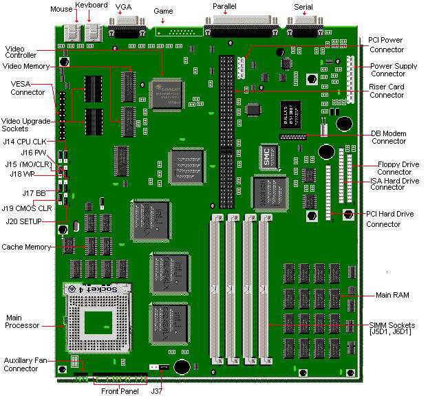
| J15 | VGA Mode | 1-2 2-3 | MONO COLOR |
| J16 | Password | 1-2 2-3 | Normal (Enabled) Clear (Disabled) |
| J17 | Flash Boot Block | 1-2 2-3 | Recovery Mode Normal ode |
| J18 | Flash Write | 1-2 2-3 | Enabled Protected |
| J19 | CMOS Clear | 1-2 2-3 | Clear Normal |
| J20 | CMOS Setup | 1-2 2-3 | Enable Disable |
| J37 | On-Board Speaker | 3-4 Open | Enable Disable |
The battery is a Dallas DS 12887 real time clock and CMOS battery integrated into the RTC chip. This chip is soldered onto the motherboard and is not replaceable.
The BIOS in the PB520 is contained in Flash EEPROM, and it can be updated via software. If the Flash BIOS is corrupted during an update, it is possible to recover it.
To run the BIOS update,
1. Insert the update diskette into drive A: and reboot the system.
2. When the opening dialogue appears, press (enter).
3. The Main Menu will appear on the screen.
4. Select "Update Flash Memory Area from a file" using the Down Arrow key.
5. Press (enter).
6. The UPDATE FLASH AREA dialog box appears on the screen.
7. Select "Update System Bios".
8. Press (enter).
9. Press the Down Arrow key to select 1009bc0r.bi0 file.
10. Press (enter).
11. Highlight the (continue with programming)option and press (enter).
12. Remove the disk from drive A and press (enter).
To recover from a corrupted BIOS, perform the following steps:
1. Turn off the system.
2. Remove the system's case and move the jumper block on J17 from pins 2-3 to pins 1-2.
3. Place the update diskette in drive A: and turn on the system.
4. There will be no video display during the BIOS recovery, this is due to the small amount of code available in the non-erasable boot block area.
5. After the system boots, it will beep once and the floppy drive light should light up. The system is copying the recovery code into the Flash EEPROM.
6. Just before the recovery completes, the system will beep twice. Once this occurs, watch the floppy drive light. When the light goes off, turn off the system.
7. Move the jumper block on J17 from pins 1-2 back to pins 2-3.
8. Turn the system on and repeat the steps for updating the BIOS.
The motherboard comes with 16KB of cache integrated in the processor ( CPU ). A secondary external cache level (write-back cache ) of 256KB is soldered on the motherboard. This cannot be upgraded.
This motherboard can accommodate any of the following CPUs.
The upgrade processor installs in the Zero Insertion Force (ZIF) socket location U2B1. Jumpers do not need to be changed.
The video memory on this system can be upgraded to 2MB, by using two 256Kx16-70ns SOJ DRAM chips.