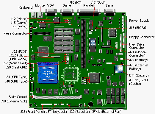

| Jumper | Description | Setting | Designation |
|---|---|---|---|
| J11 (JVGAS) | Onboard VGA | 2-3 1-2 | Enabled Disabled |
| J12 (JVD) | Colour/Monochrome | Closed Open | Monochrome Colour |
| J13 (JIRQ5/7) | LPT1 IRQ Select | 1-2 2-3 | IRQ7 IRQ5 |
| J15 (JGAME) | Game Port | Closed Open | Enabled Disabled |
| J16 (JIO) | On-Board I/O Controller | Closed Open | Enabled Disabled |
| J17 (JBOOT) | BIOS Boot Block | 2-3 1-2 | Normal Boot From Boot Block |
| J22 (JIRQ9) | Video IRQ9 | Open Closed | Disabled Enabled |
| J24 (JB8S) | On-Board Battery | Closed Open | Enabled Disabled |
| J27 (JMRQ) | Mouse Port | Closed Open | Enabled Disabled |
| J29** (JCAHS) | CPU Speed | Open Closed | 33Mhz 33Mhz |
| J39 (JSPKS) | Onboard Speaker | 2-3 1-2 | Enabled Disabled |
**If external cache is installed and computer is in de-turbo mode, having J29 closed will result in an irregular speed greater than 8 Mhz.
Use a 3.6 Volt lithium battery. Remove the shorting cap on jumper J24. Then attach the battery to connector J28, positive to pin 1, negative to pin 4.
The chips may be 25ns, 20ns, or 15ns while the Tag SRAM can be either 20ns or 15ns. The Cache and TAG RAM are either 28-pin for 32KB or 128KB of cache, or 32-pin for 512KB of cache. The PB410 uses the same cache chips as the PB430.
| J30 | J31 | J32 | J33 | |
|---|---|---|---|---|
| 32k | Open | 1-2 | 1-2 | 1-2 |
| 128k | Closed | 2-3 | 2-3 | 1-2 |
| 512k | Closed | 2-3 | 2-3 | 2-3 |
1. Revision C.0 motherboards may have the CPU installed in the upgrade socket (U45) instead of the CPU socket (U47), and will have to be removed in order to upgrade.
2. This motherboard will accommodate the P24T processor. Upgrade the BIOS to 1.01.24 or 1.01.25 before installing the P24T.
The DX4-120 CPU requires a 486 system to be able to run at 40 MHz clock speed. This motherboard will not run at that speed. However, they will run at 33 MHz which will yield 100 MHz DX4 speed.
| Rev B.0/C.0 | Rev B.0 | Rev C.0 | |||||||||
|---|---|---|---|---|---|---|---|---|---|---|---|
| U45 | J23 1-2 | J25 1-2 | J26 1-2 | J34 | J34 | J34 1-2 | J34 3-4 | J34 5-6 | J40 1-2 | J40 3-4 | J40 5-6 |
| None | - | - | - | 1-3 | 2-4 | Out | In | Out | In | Out | In |
| 486SX25 | Out | In | In | 1-3 | 2-4 | Out | Out | In | Out | In | Out |
| 487SX25 | Out | In | In | 1-3 | 2-4 | Out | In | Out | In | Out | In |
| DX2ODP50 (ODP486-25) or DX4ODP75 | Out | In | In | 1-3 | 2-4 | Out | In | Out | In | Out | In |
| DX2ODPR50 (ODPR486-25) P24T 63MHz or DX40DPR75 | Out | In | In | 3-5 | 4-6 | In | Out | In | In | Out | In |
| 486DX25 | Out | In | In | 3-5 | 4-6 | In | Out | In | In | Out | In |
| 486SX33 | Out | In | Out | 1-3 | 2-4 | Out | Out | In | Out | In | Out |
| 487SX33 | Out | In | Out | 1-3 | 2-4 | Out | In | Out | In | Out | In |
| DX2ODP66 (ODP486-33) or DX4ODP100 | Out | In | Out | 1-3 | 2-4 | Out | In | Out | In | Out | In |
| DX2ODPR66 (ODPR486-33) P24T 83MHz or DX4ODPR100 | Out | In | Out | 3-5 | 4-6 | In | Out | In | In | Out | In |
| 486DX33 | Out | In | Out | 3-5 | 4-6 | In | Out | In | In | Out | In |
| 486DX2-50 | Out | In | In | 3-5 | 4-6 | In | Out | In | In | Out | In |
| 486DX2-66 | Out | In | Out | 3-5 | 4-6 | In | Out | In | In | Out | In |
0 MB or 4 MB Standard on Motherboard 32 MB or 36 MB Maximum. The SIMM's are 256k/1MB/2MB/4MB/8MB 72-pin and can be x32 or x36. SIMM speed must be 80ns or faster. The motherboard design does not require parity checking, hence x32 SIMMs can be purchased.
Note - The motherboard with 4MB surface mount memory will not accept a 2MB SIMM.
Use a standard 8 ohm, 1/2 watt computer speaker. Move the cap on jumper J39 to pins 2 and 3, and attach the speaker to connector J38, pins 1 and 4.
Video memory is upgraded by installing a 256KBx16 70ns or 80ns DRAM ZIP at location U20. The ZIP needs to be ASYMMETRICAL (Write Enabled). This DRAM ZIP is not the same chip used for PB430/440/440T upgrades.
If the Motherboard had a DRAM chip at location (U22) the motherboard has 1MB installed. If there is not a chip at Location (U22), insert a 256KBx16 ZIP at location (U20) to upgrade the video memory to 1MB.
Check to make certain that all the legs on the chip are properly seated in the socket before pushing them in, or the chip will be damaged.