| Item | Description | Item | Description |
|---|---|---|---|
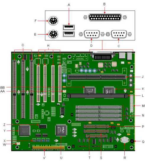
| A | USB Ports | P | Secondary IDE Connector |
| B | Parallel Port | Q | Piezo Speaker |
| C | Serial Port B | R | Battery |
| D | Serial Port A | S | Primary IDE Connector |
| E | PS/2 Keyboard Port | T | Floppy Drive Connector |
| F | PS/2 Mouse Port | U | 82371SB PIIX3 Chipset |
| G | ISA Slots | V | Front Panel Connectors |
| H | PCI Slots | W | Fan Connector |
| J | Slot1 CPU Connector | X | Jumper Block J9C1 |
| K | 82441FX PCI/Memory Controller (PMC) | Y | PC87307VUL Super I/O Controller |
| L | Heatsink Support | Z | E28F002BXT80System BIOS |
| M | Primary Power Connector | AA | Fan Power Connector |
| N | SIMM Sockets | BB | 82442FX Data Bus Accelerator |
BIOS Recovery (J9C1-A)
This jumper is for recovering BIOS data from a diskette in the event of a catastrophic failure. The default setting is pins 5-6 (normal operation). To recover the BIOS, turn off the computer, move the jumper to pins 4-5, then turn on the computer to perform BIOS recovery. After recovery, turn off the computer and return the jumper to pins 5-6 to restore normal operation.
CMOS Clear (J9C1-C)
This jumper is for resetting the CMOS settings to the default values. This procedure must be done each time the system BIOS is updated. The default setting for this jumper is pins 5-6 (keep CMOS settings). To reset the CMOS settings to the default values, turn off the computer, move the jumper to pins 4-5, then turn on the computer. When the computer displays the message "NVRAM cleared by jumper," turn off the computer and return the jumper to pins 5-6 to restore normal operation.
Password Clear (J9C1-D)
This jumper is for clearing the password if the password is forgotten. The default setting is pins 2-3, (password enabled). To clear the password, turn off the computer, move the jumper to pins 1-2, and turn on the computer. Then turn off the computer, and return the jumper to pins 2-3 to restore normal operation. If the jumper is in the 1-2 position (password disabled), you cannot set a password.
BIOS Setup Access (J9C1-D)
This jumper is for enabling or disabling access to the Setup program. The default setting is pins 5-6 (access enabled). To disable access to the Setup program, move the jumper to pins 4-5.
This 3V Lithium clip in battery is replaceable with a CR2032 battery.
The Intel Pentium II CPU has 32K level 1 cache and 512 KB level 2 cache contained in the Single Edge Contact cartridge. The cache is non-upgradeable.
This motherboard utilizes the SEC slot (SLOT1) , which is a staggered 242 pin Single Edge Contact slot. This motherboard is designed to be upgradable with any pin-compatible Intel® Pentium II processor. The speed of the processor can be set using the jumpers on the motherboard. The speed settings for the jumpers are in the table below.
| Processor/ Bus Speed | J9C1-A | J9C1-B (Processor) | J9C1-C (Bus) | Host Bus Frequency | PCI Bus Frequency | Bus/Processor Frequency Ratio |
|---|---|---|---|---|---|---|
| 233Mhz/66Mhz | 2-3 | 2-3 & 5-6 | 2-3 | 66MHz | 33MHz | 3.5 |
| 266Mhz/66Mhz | 1-2 | 1-2 & 4-5 | 2-3 | 66MHz | 33MHz | 4.0 |
| 300Mhz/66Mhz | 1-2 | 2-3 & 4-5 | 2-3 | 66MHz | 33MHz | 4.5 |
The PB760 motherboard has four SIMM sockets configured as two (0-1) banks. The upgrade memory is upgradeable to 256MB. The 72-pin SIMM sockets will accept 1MBx64 (8MB), 2MBx64 (16MB), 4MBx64 (32MB), and 8MBx64 (64MB) and 16MBx64 (128MB) extended data out DRAM SIMMs with the recommended access speed of 60ns or faster. This motherboard will accept either single or double sided SIMMs. Memory type, size, and speed can vary between sockets. This motherboard will support 36 bit SIMM modules (parity).
Once the SIMM modules are installed, the system will display the correct amount of memory, since the system automatically detects the amount installed; there are no jumper settings for memory configuration. The memory should be enabled and fully functional.
The motherboard has no on-board video graphics controller. Video RAM upgrades are dependent on the specifications of the video card being used.