Installing a video expansion card will automatically disable the on board video controller.
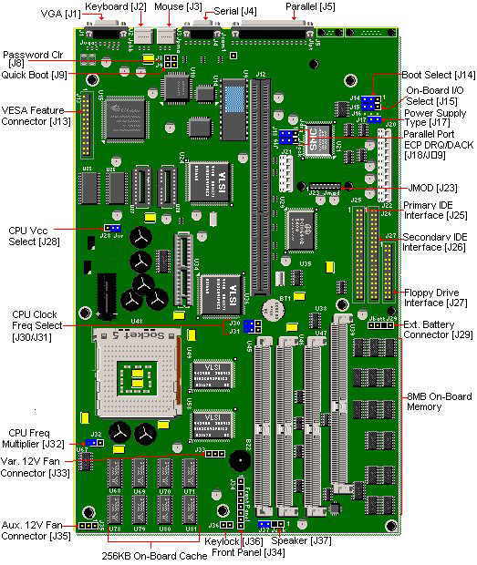
| Jumper | Function | Pin/Setting | Configuration |
|---|---|---|---|
| J8 | Password Clear | In * Out | Clear Normal |
| J9 | Quick Boot | In * Out | Quick Boot Normal |
| J14 | Boot Select | 1-2 * 2-3 | Boot Block Normal |
| J15 | On-Board I/O Select | 1-2 * 2-3 | Disabled Enabled |
| J16 | ** Parity Select | * 1-2 2-3 | Disabled Enabled |
| J17 | Power Supply Type | * In Out | Standard With Stand-by |
| J18 | Parallel Port ECP DRQ | 1-2 * 2-3 | Channel 1 Channel 3 |
| J19 | Parallel Port ECP DACK | 1-2 * 2-3 | Channel 1 Channel 3 |
| J28 | CPU VCC Select | * 1-2 2-3 | VR (+3.3V) VRE (+3.45V) |
| J29 | Battery | * In Out | On-Board Lithium battery External battery |
| J30 | Host Bus Frequency | * In Out | 60/66 MHz 50 MHz |
| J31 | Host Bus Frequency | In * Out | 66 MHz 50/60 MHz |
| J32 | Host Core Freq. Multiplier | * In Out | 2 X 1.5X |
| J37 | Speaker | * In Out | On-Board External |
* Indicates default values.
** Only if no onboard memory.
Uses a 3.0 volt lithium battery, but can be replaced with a 3.6 volt. Remove the jumper on pins 3-4 of J29 (Jbatt) battery connector. The battery connector is keyed and will only go in one way.
pin 1= +3 volts
pin 2= key
pin 3= on-board battery select
pin 4= ground
1. Insert the BIOS update diskette into drive A: and reboot the system.
2. Press (enter). When the dialogue box appears.
3. The Main Menu will appear on the screen.
4. Select "Update Flash Memory Area from a file" using the Down Arrow key.
5. Press (enter).
6. The UPDATE FLASH AREA dialog box appears on the screen.
7. Select "Update System Bios".
8. Press (enter).
9. Select 1006AU0R.BIO file.
10. Press (enter).
11. Press (enter) at the following screen to proceed with programming.
12. After 2 message screens, the BIOS is now re-programmed with the updated BIOS file.
13. Remove the disk from drive A.
14. Press (enter) to reboot the computer system.
15. Complete the process by running the CMOS Setup program.
1. The 'FLASH NORMAL/FLASH RECOVERY' jumper block,J14 is located near the Primary Power Connector,J20/J22.
2. Move the 'FLASH NORMAL/FLASH RECOVERY' jumper block,J14 from pins 2-3 to pins 1-2.
3. Insert the BIOS upgrade diskette and reboot the system. No video is available during the procedure.
4. The system beeps once and starts copying the recovery code into the CMOS Flash memory.
5. The system beeps twice as the recovery completes.
6. Turn off the system and move the jumper block,J14 from pins 1-2 to pins 2-3.
7. Leave the BIOS upgrade diskette in the floppy drive, and continue with the original upgrade following the procedure described in 'BIOS UPGRADE PROCEDURE'.
The motherboard comes with, 16KB L1 (Internal) write-back cache (integrated in the CPU) and 256KB L2 (External) write-through with write buffers cache soldered on the motherboard. Not upgradeable.
Note:
Not all motherboards come with level 2 cache
This motherboard can accommodate any of the following CPUs.
Uses 320-pin Type 5 Zero Insertion Force (ZIF) socket. Not keyboard switchable. Disable cache to slow down the system. Change switches on Jumper block SW1E1 as indicated below,
| Speed | J30 | J31 | J32 |
|---|---|---|---|
| 75MHZ | OUT | OUT | OUT |
| 90MHZ | IN | OUT | OUT |
| 100MHZ | IN | IN | OUT |
| 120MHZ | IN | OUT | IN |
| 133MHZ | IN | IN | IN |
SIMM speed must be 70ns or faster.
The SIMMs are 1/2/4/8/16/32MB 72-pin and can be x32 or x36. The motherboard's design does not require parity checking.
BIOS 1.12 and higher will support EDO SIMMs. If the BIOS is a prior version, use Fast Page SIMMs. Do not mix EDO and Fast Page memory in the same bank.
SIMMs are inserted in Bank 2 or 3, sockets U39, U47 (Bank 2), U45, and U46 (Bank 3). A bank must be filled when an upgrade is done. The system board will recognize up to 136MB of on-board memory.
NOTE - Some systems DO NOT have any RAM on-board
The PB600 can be upgraded to 2MB video memory using two 256Kx16-70ns SOJ DRAM chips. The video memory upgrade is inserted in sockets U10A1 and U11A1. Pin 1 is at the front right corner of the socket. To install the chip, insert it into the socket and push it on the chip until it snaps into place.